| |
<
Back to Articles

CFRP:A Mixed Bag of Challenges
By James Benes, American
Machinist, August 2009
| |
Because of
their very desirable strength-to-weight characteristics, carbon
fiber-reinforced polymer (CFRP) composites have long been
a favorite of aerospace designers. The use of these composites
has been more widespread in Europe than in the United States;
however, industry insiders predict CFRP composites will undoubtedly
be used in an ever increasing array of applications in this
country, particularly in the transportation industries.
Carbon fiber-reinforced polymer composites cover
a wide range of layered and matrix materials using woven carbon
fiber, resins, plastics, and can also include thin layers
of metals. However, because of the different physical properties
of the materials used in the layers that make these composites
hard, tough and strong, they are extremely abrasive and difficult
to machine. Without tools designed for the demanding cutting
environment, tool life can be very short when machining CFRP
composites. |
CFRP challenges
 The
combination of materials in CFRP — a resin matrix and carbon
fibers — presents a formidable machining challenge. The matrix
is susceptible to oxidation and degradation from excessive heat,
and the carbon fibers don’t cut well because they fracture
instead of shearing smoothly. Unlike the machining of metals that
produces continuous deformation on the shear plane to form a chip,
the machining of composites results in a series of brittle carbon-fiber
fractures producing dust-like chips that carry away very little
of the heat generated by machining. The
combination of materials in CFRP — a resin matrix and carbon
fibers — presents a formidable machining challenge. The matrix
is susceptible to oxidation and degradation from excessive heat,
and the carbon fibers don’t cut well because they fracture
instead of shearing smoothly. Unlike the machining of metals that
produces continuous deformation on the shear plane to form a chip,
the machining of composites results in a series of brittle carbon-fiber
fractures producing dust-like chips that carry away very little
of the heat generated by machining.
Another toolmaker challenge is that manufacturers
of composites are very secretive about their composite formulations,
and they tend to frequently alter these formulations. So, the performance
of a tool that had been working well might suddenly degrade because
of an unknown composite material adjustment. Then, it’s back
to the drawing board to come up with a geometry that results in
satisfactory performance.
When machining composites, using coolants can be problematic. In
many applications, the use of any foreign material — such
as a coolant — is forbidden. “I have heard of several
instances where the use of a coolant on a composite has resulted
in drilledhole shrinkage over time,” said Peter Diamantis,
plant manager at Amamco Tool.
To enhance strength and performance, hybrid structures consisting
of CFRP and metal layers, usually aluminum and/or titanium, are
used. These CFRP/metal stacks are drilled so tighttolerance holes
and patterns match on assembly. In addition to dealing with the
abrasiveness and heat sensitivity of CFRP, the conflicting drilling
requirements of the dissimilar materials in a composite/metal stack
pose a challenging problem for tool designers.
“The various combinations of metals in a composite
stack give it the characteristics necessary for the application,”
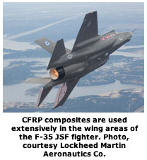
said Diamantis. “For example, an F-35 designed for land-based
operations does not require as much high-strength titanium as does
an F-35 designed for carrier operations. This is because carrier-based
aircraft are subject to a lot of physical pounding due to the short-runway
operations.”
The challenge is to develop a tool that can deal with the combination
of differing material characteristics present in a composite stack:
the relative softness of aluminum, the hardness of titanium and
the abrasiveness of the composite. The most difficult combination
is CFRP and titanium alloys because the best strategy for drilling
CFRP is high speed and a low feedrate, while the best strategy for
titanium is low speed and a high feedrate. A successful solution
involves a compromise entailing the tool’s ability to cut
each material in the stack effectively.
Effective chip evacuation is critical in drilling composites because
of the confined nature of the operation. When drilling through a
composite to a metal layer, the hard metal chips must be effectively
removed to prevent them from scarring and damaging the walls of
the composite hole. In some cases it is necessary to drill and ream
the metal layer first so chips do not have to pass through the composite
layer.
Coping with the challenges
To successfully machine CFRP, shops usually turn to the two hardest
tool materials: sharp solid-carbide tools coated with hard, long-lasting
diamond. A number of coatings are referred to as "diamond,"
including polycrystalline diamond (PCD) insert drills, vein PCD
drills, or brazed mandrel drills. But, a diamond coating applied
by the chemical-vapor-deposition (CVD) process is the only coating
that utilizes 100 percent real diamond crystals. CVD diamond coatings
reduce heat and friction created by the highly abrasive composite.
Diamond is composed of pure carbon atoms, arranged in a special
crystal orientation that gives it its unique physical properties.
At 9,000 to 10,000 Vickers, crystalline diamond is nearly twice
as hard as amorphous, diamond-like coatings.
Amorphous diamond, or diamondlike coatings, are carbon films, applied
using a physical-vapor-deposition (PVD) process, that usually are
not as thick as CVD-diamond films. They do not have a crystalline
structure and typically have about 10 percent to 15 percent the
life of CVD diamondcoated tools. And, unlike metal-sintered polycrystalline
diamond that applies a diamond tip to tooling, CVD crystalline diamond
coating enables the entire tool surface to be protected with a super
hard material. Being able to coat unique geometries provides a significant
advantage over PCD tools, which is expensive to grind.
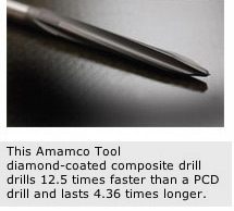
 A
new drill has been designed for CFRP applications, featuring large
relief angles for sharpness and chamfers and/or radii on the corners
to avoid wear. Beyond these common features, the drills are designed
for each application because different geometries are more or less
useful depending on the type of CFRP, which is commonly layered
with other materials. A
new drill has been designed for CFRP applications, featuring large
relief angles for sharpness and chamfers and/or radii on the corners
to avoid wear. Beyond these common features, the drills are designed
for each application because different geometries are more or less
useful depending on the type of CFRP, which is commonly layered
with other materials.
The drill is coated by a unique CVD diamond coating process that
overcomes the tendency of a CVD coating to round a tool’s
cutting edge that could offset any toollife gains by reducing sharpness.
The duller the tool, the less likely it is to make a clean cut that
avoids delaminating the material.
The custom coating application methodology keeps the micro-grain
structure of the diamond crystals to less than one micron. This
allows the coating to conform closely to the contours of the cutting
edge, to maintain sharpness while providing the necessary tool life.
Amamco’s Diamantis has had the best success with tools coated
with pure diamond. “Diamond-like coated tools work well in
some applications and are less expensive, but they don’t last
as long as pure diamond. Other tool coatings typically used on tools
for cutting aluminum or titanium are quickly destroyed by the extreme
abrasiveness of composites.”
The ability of a diamond coating to increase tool life and prevent
composite delamination was demonstrated in a tooling development
program conducted by the National Center for Defense Manufacturing
& Machining (NCDMM) under the auspices of Lockheed Martin Aeronautics
Co. (LMAC) manufacturer of composite components for the F-35 Joint
Strike Fighter.
The resulting tool for machining composites relies heavily on DiaTiger,
a CVD diamond coating produced by Diamond Tool Coating. The drills
excel in carbon fiber composite applications, significantly increasing
the number holes drilled in aircraft wing-skins compared with PCD
tooling. The new tool design and material increased tool life from
9 l inear f t at one- thi rd mater ial thickness to 57 linear ft
at full material thickness. Now, LMAC can machine a complete wingskin
using only two tools, one to rough and one to finish, instead of
the 24 cutting tools used. Resulting cost savings per aircraft is
about $80,000.
How They're Made
The reinforcing carbon fiber is produced by thermal decomposition
of polyacrylonitrile (PAN). The thermal decomposition converts
the PAN fiber to a pure carbon fiber that is highly abrasive
yet very strong. Carbon fibers are reported to have tensile
strengths of about 800,000 psi and a modulus of 40 million psi.
These high-strength fibers are woven into thin sheets and combined
with resins to form prepregs. The composite skin section of
an aircraft is normally produced by placing multiple layers
of this prepreg in molds and then using pressure and heat to
cure the CFRP into a complex wing surface. The carbon fibers
also can be chopped and blended with resins to form structural
parts and then processed by compression molding or resin-transfer
molding. |
|


 The
combination of materials in CFRP — a resin matrix and carbon
fibers — presents a formidable machining challenge. The matrix
is susceptible to oxidation and degradation from excessive heat,
and the carbon fibers don’t cut well because they fracture
instead of shearing smoothly. Unlike the machining of metals that
produces continuous deformation on the shear plane to form a chip,
the machining of composites results in a series of brittle carbon-fiber
fractures producing dust-like chips that carry away very little
of the heat generated by machining.
 A
new drill has been designed for CFRP applications, featuring large
relief angles for sharpness and chamfers and/or radii on the corners
to avoid wear. Beyond these common features, the drills are designed
for each application because different geometries are more or less
useful depending on the type of CFRP, which is commonly layered
with other materials.